Plot Clock
Ruichen Dong(rd568) and Weiyang Fan(wf227)
December 10,2019.
Demonstration Video
Introduction
Nowadays we live in a fast-pace time precious society. Sometimes people may want slow down and take a break. In this project ,we developed the plot clock for the purpose of slowing people down. Plot clock is a raspberry pi based self-driven robot. It can write down the current time on a white board in a very inefficient way, then wipe out everything on the white board and write down the updated time again. Hope this funny clock can make you happy.
Project Objective:
- Develop algorithm to simulate trajectory of the pen.
- Automate the clock to write down current time.
- Automate the clock to grab the eraser and wipe out the writing on the board.
Design and testing
The design of project can be split into four parts:Hardware,Electrical,Software and Algorithm. In the following section we will briefly introduce the idea of each part and how we design them.
Hardware Design
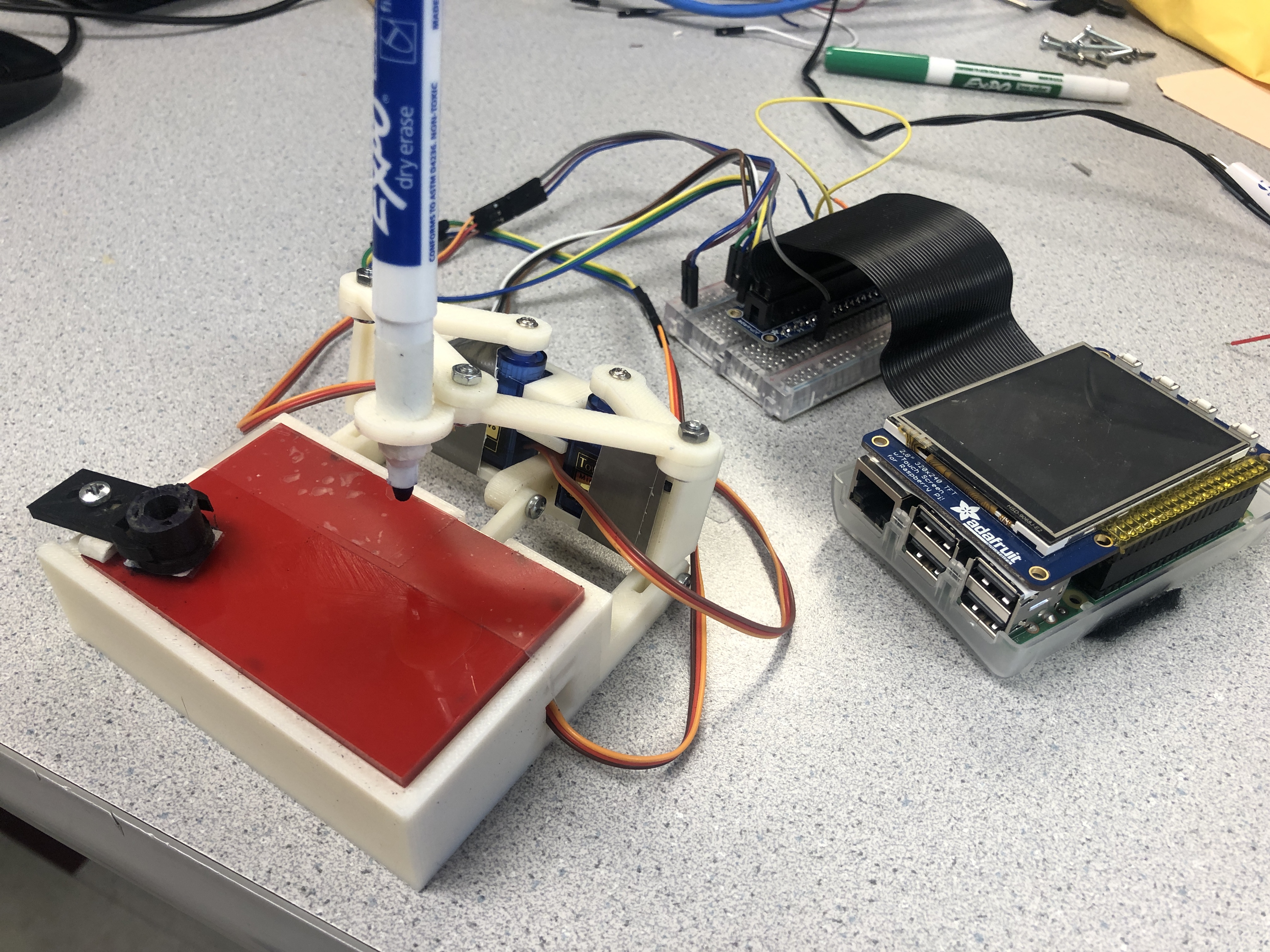
The mechanical structure of plot clock is listed as followed. It is driven by three servos and raspberry pi.
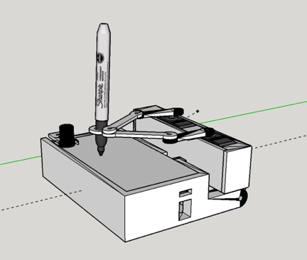
The arm holding the marker pen is attached to the servos by M3 screw. Change of the angle of servos will lead to movement of the arms. In this way we can control the trajectory of the pen and make the plot clock to write down different numbers.
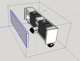
The servos are held by a servo box. This box makes sure the servos keep still and fix their position.
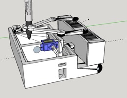
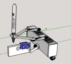
Other than moving the pen horizontally , we need to lift up or put down the pen to achieve clear writing. We achieved this by attaching a servo to the case. The servo is connected to the servo box with a short arm. By adjusting the angle of the servo, the servo box can be lift up and put down accordingly.
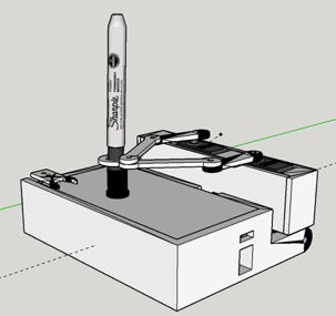
The eraser is specially designed for the marker pen. It can be seen as the pen cap ,and we attached a piece of fuzzy on the back side of the eraser. The plot clock can hold the eraser by insert the marker pen into the eraser. Then the plot clock can wipe out the writing by moving the eraser on the white board.
Electrical Design
The electrical part of this project is quite simple. As mentioned before we only use three servos to drive the plot clock.
Parallax Continuous Rotation Servo
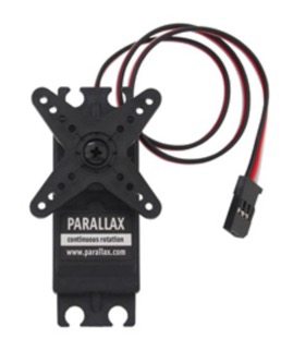
At the beginning of the project, we planed to use Parallax Continuous Rotation Servo to control the arm .We can control the servo to stop at a certain angle by adjusting the However, after experiment we found that this servo is not stable. The outcome of the same dutycycle varies form time to time. To achieve clear writing ,we need servos with error less than 2 degree.
SG90 Control
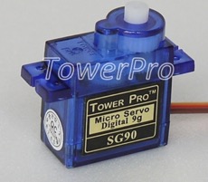
To achieve accurate control over the movement of the pen. We decided to use SG90 servo from TowerPro. SG90 servo can be controlled by PWM. The servo will rotate to a certain angle according to the received PWM signal.
Circuit Diagram
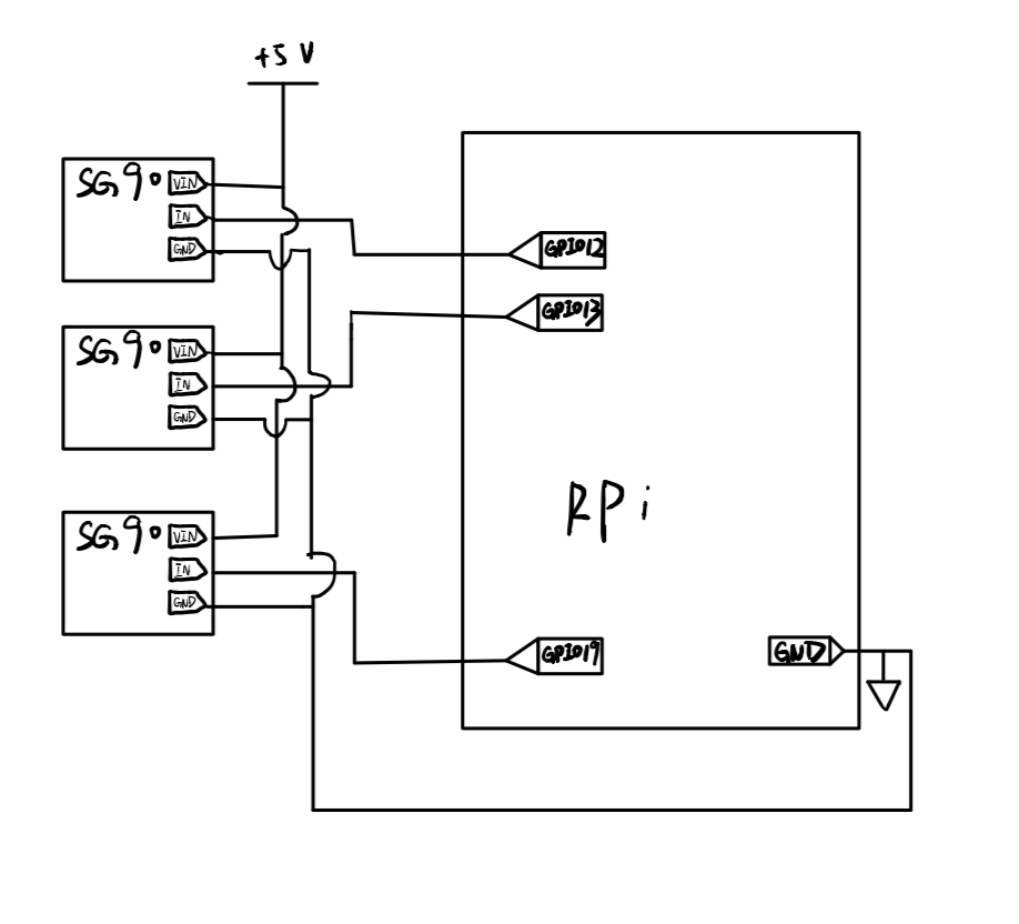
The figure above shows the Circuit diagram of this project
Algorithm Design
In this project, we use two servo’s angle to control the position of the pen. To make the this math problem easier. We set up a coordinate system to model the relationship between the angle of the servos and position of the pen.
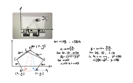
A and B stand for two servo ,AC,CE,BF,DF are the arms holding the pen. D is the position of the pen. What we want is the size of ∠DAB and∠FBG.We can get ∠α and ∠β by arctan formation. Then according to the law of cosine , we can get ∠CAD,then get the target angle by sum up ∠α and ∠CAD.In the same way we can get ∠FBG.This is a representative situation of this project. But the basic idea of the algorithm is the same. Calculate the angle of both servos according to the position of the pen by math and geometric.Then control the pen to move to any position we want by adjusting the angle of the servos.
Software Design
We designed our software by modules, and the modules have been splited into many functions to achieve the precise control of the hardware. The first part is the control of the servo. Since we want to use servo to drive the arms which connect to the pen to accomplish the plotting, the precise contol of the pen is our first target. Here are some related functions:
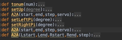
We used pigpio to write the hardware PWM to the two servos to achieve a stable control. In the function setLeftPi and setRightPi, the input degree is the degree that we want that two servos to perform. Through the usage of these two functions, the two servos can be set to any angle we want. There is also a third servo which is controlled by the software GPIO. We used this servo to lift up or put down the pen. A2A function was designed to control the angle of this servo during the plotting process.
After designed the control of the servo, we continued to design the algorithm for use these servos to draw on the board. This is the core function in the whole project, as mentioned in algorithm design section, we built up the relationship between the position of the pen on the board and the angle of two servos. The code for this part is listed as followed:
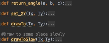
In the function set_XY,input is the target position x and y on the board. The output for the function is the angel for the two servos. We use the python code to achieve the mathematic conversion and calculate the value we want. The drawTo method further use the angle value we get from a specific position and drive the arms to move on the board for a distance to achieve the function of drawing. The drawToSlow have the same function as the drawTo, but we design it with a slower speed for movement to achieve a more stable movement.
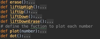
The last part for the functions is the drawing functions. We use these function to plot the number on the board. We design these function as the high-level function, which means that they will only handle the logic for plotting and just call the basic(low-level) function that we have already designed before. The erase() will catch the eraser and then move with eraser to erase the plotting on the board. There are for functions related to the pen lift up and down. We design two height of lifting, one is for the lift function during the plotting numbers, and the other is for catch the eraser.
The plot() function is also a core algorithm for the whole project. The input is the number need to be plotted. We design the algorithm for numbers form 0 to 9 separately. In order to achieve the effect that the four digital number show on the board in order, we used a parameter LOCATION to count the position of the number. The value of the LOCATION can be 0, 1, 2, 3. Every time we plot a number, we will add this parameter and it will repeat in a loop. By this way, the new number we plot can appear on correct position on the board. The dot() function will plot two dot on the board to make it looks more like a really digital clock.
Test
The majority of the work in the test part for our software is to test whether our software can plot the numbers in a good effect as we expected. We design eleven version of the software code before we decide the final version. Each version of the code have some improvements and new functions on the previous version. We design the code and then go back to test the function we added and the function we have already test before to make sure that the new version performed well. The most time consuming part in the test phases is to acquire the best plotting pattern. We modify the parameters we set in the code, and repeat testing until we get a satisfactory numbers on the board.Here is a video of a plot clock writing number in an ideal condition.
Result
In a whole, the project progressed as we planned in the beginning. However, we still met a lots of problem in the progress. The model made by 3D printer takes more time than we imagine and a delay in the whole schedule. We also spent a lots of time to explore the usage of the servo to implements the function that we want to achieve in our machine. We also find that the development of the algorithm to plot different numbers on the board is easier than we thought in the beginning, so we save some time and compensate for the delay in the previous period. We basically met the goals that we outlined in the description of the project. All the function is achieved. And the final result is quiet good as we expected in the beginning.The following video shows how our clock work.
Conclusion
During this project, we designed and implemented a plot clock which can plot the time on the board and update the current. We achieved the goal we set in the projetc proposal. For the plot clock machine that we made in the project, we achieve the control of the clock, the clock can plot the time on the board with 4 digital numbers, the clock can catch the eraser to erase the time on the board and the clock can continually update current time on board. However, we fail to achieve the GUI control over the clock. We found PiTFT is not compatible with the servo we use and the servo may lose control when PiTFT is connect to the Raspberry Pi.This may casued by the disturbance of Pygame running in the background.So instead we implemented external buttons to control the plot clock.
Future work
The first part we want to improve is to explore the usage of the a better servo, a more stable and precise servo with large torte. Though the servo on our machine is good enough to perform the plotting tasks on the board, but we still find that it is not stable and precise. Sometime, the number plotted is not clear enough to be recognized. We think a better servo is a solution.
Then we want to acquire a more accurate current time. For the time to be plotted on the board, we now us the time get from the internet when Raspberry Pi is connected to the Internet. However, we found that the time we get sometimes is not accurate and there may be some deviation to the accurate time. We thought about to add a precise time clock sensor to it to catch the current time to solve this problem.
Another part that can be improved is the erase function. In our design, the clock will find the eraser on the corner of the board and grab it to erase the writing on the board.However,We found that the material covered on the eraser sometimes do not perform well. Some writing still remain on the board. We can try different materials to figure out which have the best cleaning effect.
Work Distribution
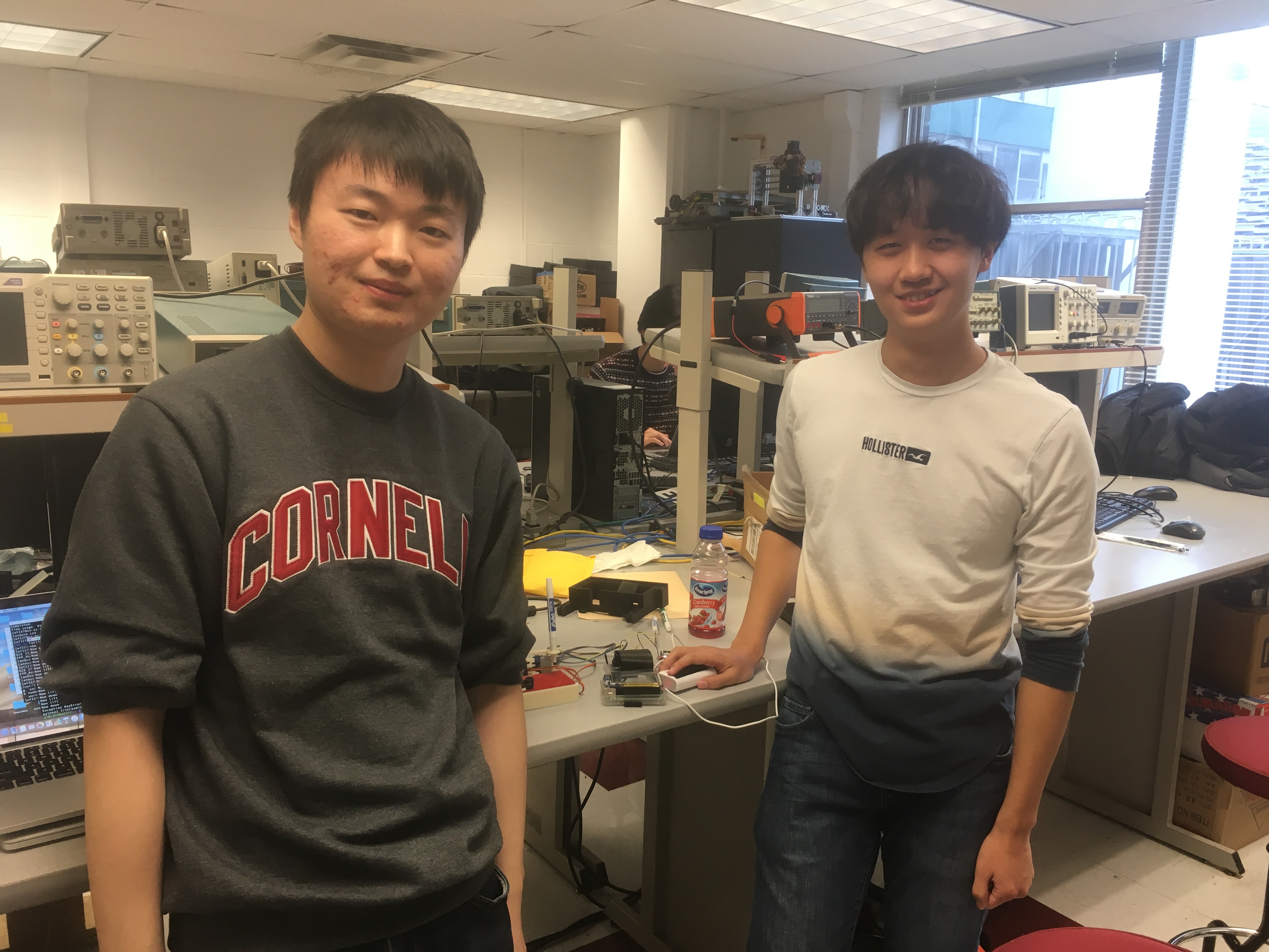
Project group picture
Ruichen Dong
rd568@cornell.edu
Mechanical desian and 3D modelling
Algorithm development
Testing
Weiyang Fan
wf227@cornell.edu
Software development
Algorithm development
Testing
>
Parts List
- Raspberry Pi $35.00
- SG90 Servo $8.88
- Buttons, Resistors and Wires - Provided in lab
- 3D Print Model - Provide by RPL
Total: $43.88
Code Appendix
import RPi.GPIO as GPIO
import math
import pigpio
import time
import signal
import atexit

TOTALX = 84
TOTALY = 52
LOCATION = 0 #the location of the number on the board. can be 0,1,2,3
L1=35
L2=55.1
L3=13.2
L4 = 45
#Global varible descibing current position of the pen
Current_x=0
Current_y=0
#The step we use in draw to slowly
STEP=4
#plot range on the board
RANGE_LEFT    =  0
RANGE_RIGHT   = 44
RANGE_SLOT    = (RANGE_RIGHT - RANGE_LEFT)/4
RANGE_UP      = 40 # upper bound of the number
RANGE_DOWN    = 30 # lower bound of the number
BLOCK_WIDTH   = 5#the width for each number on the board

# position for the eraser
eraser_posX = 72
eraser_posY = 44

CURRENT_LIFT_POSITION=0
# position for left servo
O1X=22
O1Y=-25
# posistion for right servo
O2X=47
O2Y=-25
delay=1 #delat time
LEFT_PIN=12
RIGHT_PIN=13
LIFT=False
ERASER_LIFT = False
pi=math.pi
pre_time = 0000


hw_pi=pigpio.pi()
GPIO.setmode(GPIO.BCM)
GPIO.setup(17,GPIO.IN,pull_up_down=GPIO.PUD_UP)
GPIO.setup(27,GPIO.IN,pull_up_down=GPIO.PUD_UP)
GPIO.setup(19, GPIO.OUT)
p1=GPIO.PWM(19,50)
hw_pi.hardware_PWM(12,0,0)
hw_pi.hardware_PWM(13,0,0)
time.sleep(0.5)
hw_pi.stop()
hw_pi=pigpio.pi()

def GPIO17_callback(channel):
   exit()
GPIO.add_event_detect(17, GPIO.FALLING, callback=GPIO17_callback, bouncetime=300)


def GPIOtonum(num):
    fm=10.0/180.0
    num=num*fm+2.5
    num=int(num*10)/10.0
    return num

def setLeft(degree):
    hw_pi.hardware_PWM(LEFT_PIN,50,tonum(degree))

def setRight(degree):
    hw_pi.hardware_PWM(RIGHT_PIN,50,tonum(degree))

def tonum(num):
    fm=100000.0/180.0
    num=num*fm+25000
    #num=int(num*10)/10.0
    return num
def setUp(degree):
    hw_pi.hardware_PWM(LEFT_PIN,50,tonum(0))
    hw_pi.hardware_PWM(RIGHT_PIN,50,tonum(0))
def A2A(start,end,step,servo):  #If servo is true ,rotate Left servo.Else rotate right servo
    each=(end-start)/(step+0.0)
    current=start
    if(servo):
        pin=LEFT_PIN
    else:
        pin=RIGHT_PIN
    while(current<end+step):
        hw_pi.hardware_PWM(pin,50,tonum(current))
        time.sleep(0.1)
        current=current+each
def setLeftPi(degree):
    degree=(degree*180)/math.pi
    hw_pi.hardware_PWM(LEFT_PIN,50,tonum(degree))
def setRightPi(degree):
    degree=(degree*180)/math.pi
    hw_pi.hardware_PWM(RIGHT_PIN,50,tonum(degree))
def A2A(start,end,step,servo):  #If servo is true ,rotate Left servo.Else rotate right servo
    each=(end-start)/(step+0.0)
    current=start
    if(servo):
        pin=LEFT_PIN
    else:
        pin=RIGHT_PIN
    while(current<end+step):
        hw_pi.hardware_PWM(pin,50,tonum(current))
        time.sleep(0.1)
        current=current+each
def A2A(Lstart,Lend,Rstart,Rend,step):
    Leach=(Lend-Lstart)/(step+0.0)
    Reach=(Rend-Rstart)/(step+0.0)
    Lcurrent=Lstart
    Rcurrent=Rstart
    while(current<end+step):
        hw_pi.hardware_PWM(pin,50,tonum(current))
        time.sleep(0.1)
        current=current+each

def return_angle(a, b, c):
    return math.acos((a * a + c * c - b * b) / (2 * a * c));

def set_XY(Tx, Ty):
    time.sleep(1)
    dx = Tx - O1X
    dy = Ty - O1Y

    c = math.sqrt(dx**2 + dy**2)
    if(dx==0):
        a1=pi/2
    else:
        a1 = math.atan(dy/dx)

    if(a1 < 0):
        a1 = a1 + math.pi
    a2 = return_angle(L1, L2, c);

    angle1 = a1 + a2

    # print(angle1)

    #caculate the angel for the right servo
    a2 = return_angle(L2, L1, c)
    Hx = Tx + L3 * math.cos((a1 - a2 + 0.621) + math.pi)
    Hy = Ty + L3 * math.sin((a1 - a2 + 0.621) + math.pi)
    # print('HX' + str(Hx))
    # print('hy' + str(Hy))

    dx = Hx - O2X
    dy = Hy - O2Y

    c = math.sqrt(dx * dx + dy * dy)
    if(dx==0):
        a1=pi/2
    else:
        a1 = math.atan(dy/dx)
    if(a1 < 0):
        a1 = a1 + math.pi

    a2 = return_angle(L1, L4, c)
    angle2 = a1 - a2
    # print(angle2)

    return angle1, angle2

def drawTo(Tx, Ty):
    global Current_x,Current_y
    x, y = set_XY(Tx, Ty)
    setLeftPi(x)
    setRightPi(y)
    Current_x=Tx
    Current_y=Ty
    time.sleep(0.1)

#Draw to some place slowly
def drawToSlow(Tx,Ty):
    global Current_x,Current_y
    global STEP
    temp=STEP
    Each_step_x=(Tx-Current_x)/temp
    Each_step_y=(Ty-Current_y)/temp
    while(temp>0):
        drawTo(Current_x+Each_step_x,Current_y+Each_step_y)
        temp=temp-1
    time.sleep(0.1)

# the function to erase the number on the screen
def erase():
    liftUpHigh()
    drawToSlow(eraser_posX, eraser_posY)
    time.sleep(1)
    liftDownErase()
    drawTo(40,20)
    drawTo(0, 40)
    drawTo(40, 40)
    drawTo(40, 30)
    drawTo(0, 30)
    drawTo(0, 40)
    drawTo(40, 40)
    drawTo(40, 30)
    drawTo(0, 30)
    drawTo(0, 40)
    drawTo(40, 40)
    drawTo(40, 30)
    drawTo(0, 30)
    drawTo(40,20)
    drawToSlow(eraser_posX, eraser_posY)
    liftUpHigh()
    drawToSlow(30,20)
def liftUpHigh():
    global ERASER_LIFT
    global CURRENT_LIFT_POSITION
    print("Now lift")
    if (ERASER_LIFT):
        return
    temp = STEP
    Each_step = (60 - CURRENT_LIFT_POSITION) / temp
    while (temp > 0):
        CURRENT_LIFT_POSITION = CURRENT_LIFT_POSITION + Each_step
        p1.ChangeDutyCycle(GPIOtonum(CURRENT_LIFT_POSITION))
        temp = temp - 1
        time.sleep(1)
    CURRENT_LIFT_POSITION = 60
    time.sleep(1)
    ERASER_LIFT = True
def liftUp():
    global LIFT
    print("Now lift")
    if (LIFT):
        return
    p1.ChangeDutyCycle(GPIOtonum(20))
    CURRENT_LIFT_POSITION = 20
    time.sleep(1)
    LIFT = True
def liftDown():
    global LIFT
    print("Now down")
    if (not LIFT):
        return
    p1.ChangeDutyCycle(GPIOtonum(0))
    CURRENT_LIFT_POSITION = 0
    time.sleep(1)
    LIFT = False
def liftDownErase():
    global ERASER_LIFT
    global CURRENT_LIFT_POSITION
    print("Now down")
    if (not ERASER_LIFT):
        return
    temp = STEP
    Each_step = (CURRENT_LIFT_POSITION - 0) / temp
    while (temp > 0):
        CURRENT_LIFT_POSITION = CURRENT_LIFT_POSITION - Each_step
        p1.ChangeDutyCycle(GPIOtonum(CURRENT_LIFT_POSITION))
        temp = temp - 1
        time.sleep(1)
    CURRENT_LIFT_POSITION = 0
    time.sleep(1)
    ERASER_LIFT = False
# define the fuction to plot each number
def plot(number):
    global LOCATION
    global RANGE_LEFT
    global RANGE_RIGHT
    global RANGE_SLOT
    global RANGE_UP
    global RANGE_DOWN
    global BLOCK_WIDTH

    if(number==1):
        liftUp()
        drawToSlow(RANGE_LEFT + LOCATION*RANGE_SLOT+BLOCK_WIDTH,RANGE_UP)
        liftDown()
        drawToSlow(RANGE_LEFT + LOCATION*RANGE_SLOT+BLOCK_WIDTH,RANGE_DOWN)
        liftUp()

    elif(number==0):
        liftUp()
        drawToSlow(RANGE_LEFT + LOCATION * RANGE_SLOT, RANGE_UP)
        liftDown()
        drawToSlow(RANGE_LEFT + LOCATION * RANGE_SLOT + BLOCK_WIDTH, RANGE_UP)
        drawToSlow(RANGE_LEFT + LOCATION * RANGE_SLOT + BLOCK_WIDTH, RANGE_DOWN)
        drawToSlow(RANGE_LEFT + LOCATION * RANGE_SLOT , RANGE_DOWN)
        drawToSlow(RANGE_LEFT + LOCATION * RANGE_SLOT, RANGE_UP)
        liftUp()
    elif(number==2):
        liftUp()
        drawToSlow(RANGE_LEFT + LOCATION * RANGE_SLOT, RANGE_UP)
        liftDown()
        drawToSlow(RANGE_LEFT + LOCATION * RANGE_SLOT + BLOCK_WIDTH, RANGE_UP)
        drawToSlow(RANGE_LEFT + LOCATION * RANGE_SLOT + BLOCK_WIDTH, (RANGE_DOWN+RANGE_UP)/2)
        drawToSlow(RANGE_LEFT + LOCATION * RANGE_SLOT, (RANGE_DOWN + RANGE_UP) / 2)
        drawToSlow(RANGE_LEFT + LOCATION * RANGE_SLOT, RANGE_DOWN)
        drawToSlow(RANGE_LEFT + LOCATION * RANGE_SLOT + BLOCK_WIDTH, RANGE_DOWN)
        liftUp()
    elif(number==3):
        liftUp()
        drawToSlow(RANGE_LEFT + LOCATION * RANGE_SLOT, RANGE_UP)
        liftDown()
        drawToSlow(RANGE_LEFT + LOCATION * RANGE_SLOT + BLOCK_WIDTH, RANGE_UP)
        drawToSlow(RANGE_LEFT + LOCATION * RANGE_SLOT + BLOCK_WIDTH, RANGE_DOWN)
        drawToSlow(RANGE_LEFT + LOCATION * RANGE_SLOT, RANGE_DOWN)
        liftUp()
        drawToSlow(RANGE_LEFT + LOCATION * RANGE_SLOT + BLOCK_WIDTH, (RANGE_DOWN+RANGE_UP)/2)
        liftDown()
        drawToSlow(RANGE_LEFT + LOCATION * RANGE_SLOT, (RANGE_DOWN+RANGE_UP)/2)
        liftUp()
    elif(number==4):
        liftUp()
        drawToSlow(RANGE_LEFT + LOCATION * RANGE_SLOT, RANGE_UP)
        liftDown()
        drawToSlow(RANGE_LEFT + LOCATION * RANGE_SLOT, (RANGE_UP+RANGE_DOWN)/2)
        drawToSlow(RANGE_LEFT + LOCATION * RANGE_SLOT + BLOCK_WIDTH, (RANGE_UP+RANGE_DOWN)/2)
        liftUp()
        drawToSlow(RANGE_LEFT + LOCATION * RANGE_SLOT + BLOCK_WIDTH, RANGE_UP)
        liftDown()
        drawToSlow(RANGE_LEFT + LOCATION * RANGE_SLOT + BLOCK_WIDTH, RANGE_DOWN)
        liftUp()
    elif(number==5):
        liftUp()
        drawToSlow(RANGE_LEFT + LOCATION * RANGE_SLOT, RANGE_UP)
        liftDown()
        drawToSlow(RANGE_LEFT + LOCATION * RANGE_SLOT, (RANGE_UP+RANGE_DOWN)/2)
        drawToSlow(RANGE_LEFT + LOCATION * RANGE_SLOT + BLOCK_WIDTH, (RANGE_UP+RANGE_DOWN)/2)
        drawToSlow(RANGE_LEFT + LOCATION * RANGE_SLOT + BLOCK_WIDTH, RANGE_DOWN)
        drawToSlow(RANGE_LEFT + LOCATION * RANGE_SLOT, RANGE_DOWN)
        liftUp()
        drawToSlow(RANGE_LEFT + LOCATION * RANGE_SLOT, RANGE_UP)
        liftDown()
        drawToSlow(RANGE_LEFT + LOCATION * RANGE_SLOT + BLOCK_WIDTH, RANGE_UP)
        liftUp()
    elif(number==6):
        liftUp()
        drawToSlow(RANGE_LEFT + LOCATION * RANGE_SLOT, RANGE_UP)
        liftDown()
        drawToSlow(RANGE_LEFT + LOCATION * RANGE_SLOT, RANGE_DOWN)
        drawToSlow(RANGE_LEFT + LOCATION * RANGE_SLOT + BLOCK_WIDTH, RANGE_DOWN)
        drawToSlow(RANGE_LEFT + LOCATION * RANGE_SLOT + BLOCK_WIDTH, (RANGE_UP+RANGE_DOWN)/2)
        drawToSlow(RANGE_LEFT + LOCATION * RANGE_SLOT, (RANGE_UP+RANGE_DOWN)/2)
        liftUp()
    elif(number==7):
        liftUp()
        drawToSlow(RANGE_LEFT + LOCATION * RANGE_SLOT, RANGE_UP)
        liftDown()
        drawToSlow(RANGE_LEFT + LOCATION * RANGE_SLOT + BLOCK_WIDTH, RANGE_UP)
        drawToSlow(RANGE_LEFT + LOCATION * RANGE_SLOT + BLOCK_WIDTH, RANGE_DOWN)
        liftUp()
    elif(number==8):
        liftUp()
        drawToSlow(RANGE_LEFT + LOCATION * RANGE_SLOT, RANGE_UP)
        liftDown()
        drawToSlow(RANGE_LEFT + LOCATION * RANGE_SLOT + BLOCK_WIDTH, RANGE_UP)
        drawToSlow(RANGE_LEFT + LOCATION * RANGE_SLOT + BLOCK_WIDTH, RANGE_DOWN)
        drawToSlow(RANGE_LEFT + LOCATION * RANGE_SLOT, RANGE_DOWN)
        drawToSlow(RANGE_LEFT + LOCATION * RANGE_SLOT, RANGE_UP)
        liftUp()
        drawToSlow(RANGE_LEFT + LOCATION * RANGE_SLOT, (RANGE_UP+RANGE_DOWN)/2)
        liftDown()
        drawToSlow(RANGE_LEFT + LOCATION * RANGE_SLOT + BLOCK_WIDTH, (RANGE_UP + RANGE_DOWN)/2)
        liftUp()
    elif(number==9):
        liftUp()
        drawToSlow(RANGE_LEFT + LOCATION * RANGE_SLOT + BLOCK_WIDTH, (RANGE_UP+RANGE_DOWN)/2)
        liftDown()
        drawToSlow(RANGE_LEFT + LOCATION * RANGE_SLOT, (RANGE_UP + RANGE_DOWN) / 2)
        drawToSlow(RANGE_LEFT + LOCATION * RANGE_SLOT, RANGE_UP)
        drawToSlow(RANGE_LEFT + LOCATION * RANGE_SLOT + BLOCK_WIDTH, RANGE_UP)
        drawToSlow(RANGE_LEFT + LOCATION * RANGE_SLOT + BLOCK_WIDTH, RANGE_DOWN)


    LOCATION = LOCATION + 1
    if (LOCATION == 4):
        LOCATION = 0
def dot():
    global LOCATION
    global RANGE_LEFT
    global RANGE_RIGHT
    global RANGE_SLOT
    global RANGE_UP
    global RANGE_DOWN
    global BLOCK_WIDTH
    liftUp()
    drawTo(RANGE_LEFT +2*RANGE_SLOT -(RANGE_SLOT-BLOCK_WIDTH)/2, RANGE_UP-2)
    liftDown()
    liftUp()
    drawTo(RANGE_LEFT + 2*RANGE_SLOT -(RANGE_SLOT-BLOCK_WIDTH)/2, RANGE_DOWN+3)
    liftDown()
    liftUp()

print "Waiting for falling edge on port 27"
GPIO.wait_for_edge(27, GPIO.FALLING)
print "Falling edge detect on port"
p1.start(GPIOtonum(60))


drawTo(10,40)


time.sleep(2)

time.sleep(1)

print("now")


while(True):
    cur_time = time.strftime('%H%M',time.localtime(time.time()))
    if(cur_time==pre_time):
        continue
    else:
        print("Now erase!")
        erase()
        drawTo(20,30)
        #print(type(1))
        #print(type(int(cur_time[0])))
        plot(int(cur_time[0]))
        plot(int(cur_time[1]))
        dot()
        plot(int(cur_time[2]))
        plot(int(cur_time[3]))
        pre_time = cur_time

# erase()
print('finished')